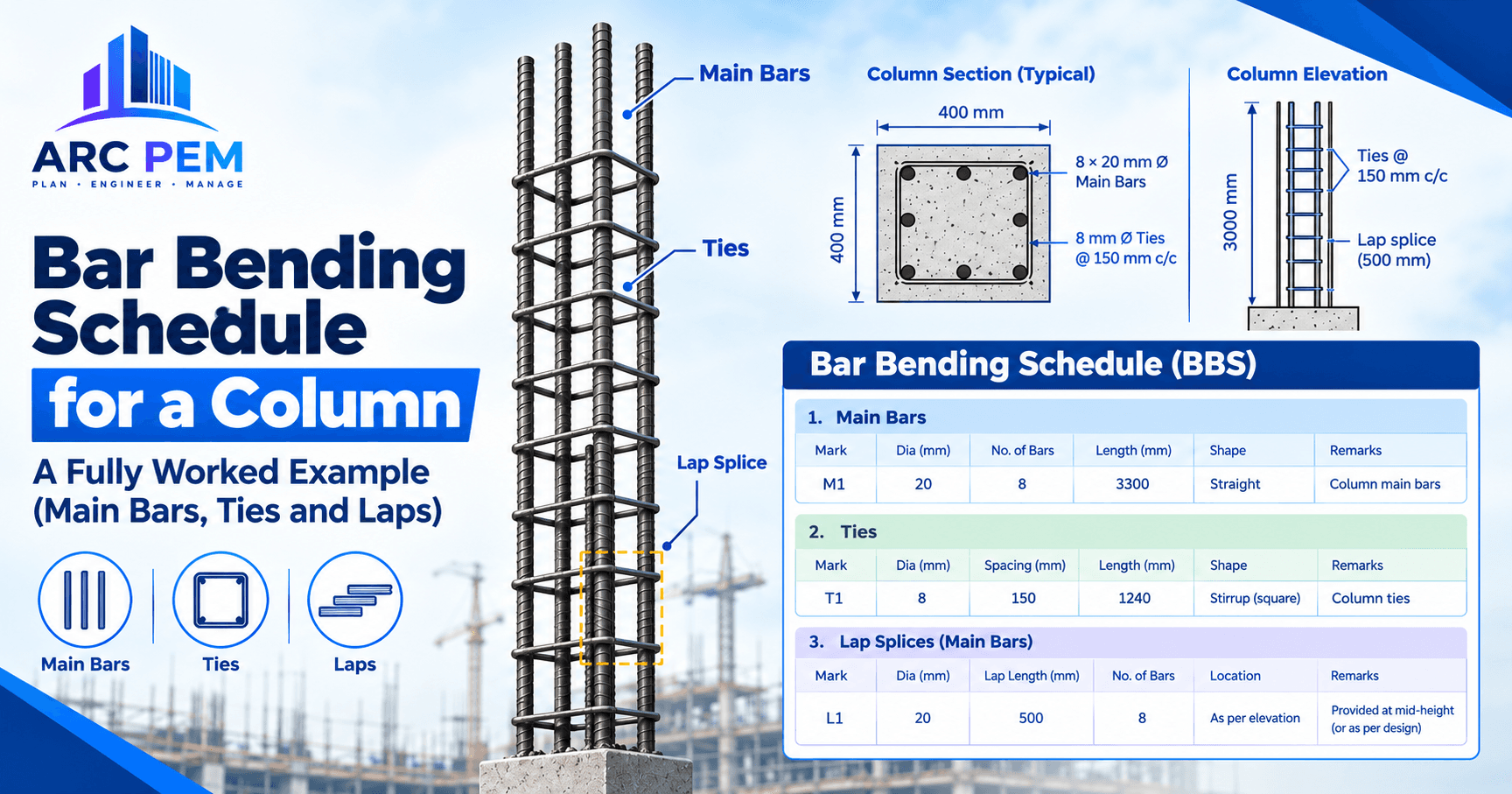
A bar bending schedule (BBS) for a column lists each bar mark in the column with its diameter, shape, number, cutting length and weight. For a rectangular tied column there are only two bar marks to work out: the vertical main bars and the lateral ties.
Quick answer:
- Main bar cutting length = footing embedment + column height + lap above + foot length − bend deduction (2d for each 90° bend)
- Tie cutting length = 2 × (a + b) + 12d, where a and b are the column width and depth minus twice the clear cover
- Number of ties = column height ÷ spacing + 1
- Weight = length in metres × d² ÷ 162 kg/m
For the 300 × 300 mm column below, that gives a 4235 mm main bar, a 976 mm tie, 21 ties and about 34.9 kg of steel for one column lift.
This is the third post in our BBS series. In the first post we showed that BBS numbers come from three mechanisms: force diagrams (shape), bend geometry (deductions) and bond stress (anchorage and laps). In the beam example we applied them to a simply supported beam. Here we apply them to a column, where laps matter far more.
The Column
| Item | Value |
|---|---|
| Section | 300 × 300 mm |
| Height | 3.0 m from top of footing to top of floor slab |
| Footing | 500 mm thick, 50 mm bottom cover |
| Materials | M25 concrete, Fe500 steel |
| Clear cover | 40 mm |
| Main bars | 4 nos. 16φ, one in each corner |
| Ties | 8φ @ 150 mm c/c, 135° hooks |
Conventions used in this example:
- All dimensions are out-to-out.
- Bend deduction is 2d for each 90° bend.
- Ties follow the SP-34 convention our calculator uses: a 9d allowance for each 135° hook, and deductions for the three effective 90° corner bends.
- The foot of the main bar in the footing is 12d. This is a detailing assumption, so use the value on your own drawing.
- Weight per metre = d² ÷ 162, which gives 1.580 kg/m for 16φ and 0.395 kg/m for 8φ.
Step 1: How Do You Calculate the Cutting Length of a Column Main Bar?
A column's main bars do three jobs. They start in the footing, run the full height of the column, and stick out above the floor so the next lift can be spliced onto them. Each job adds length.
- Embedment in the footing = 500 − 50 = 450 mm
- Column height = 3000 mm
- Lap above the floor = 625 mm (worked out in Step 2)
- Vertical run, out-to-out = 450 + 3000 + 625 = 4075 mm
- Foot at the base = 12d = 12 × 16 = +192 mm
- Bend deduction = 1 bend × 2d = −32 mm
- Cutting length = 4075 + 192 − 32 = 4235 mm
- Weight = 4 bars × 4.235 m × 1.580 kg/m = 26.77 kg
All three mechanisms are at work in this one bar. The L-shape at the base comes from how the column loads pass into the footing (shape). The 32 mm deduction comes from the bend geometry. And the 450 mm embedment and 625 mm lap both come from bond stress: the concrete needs enough bar surface to grip.
The upper-floor bars start at floor level and run alongside these starters for the lap length. So each lift's bars are scheduled as floor height plus the lap above, with the footing embedment and foot only on the ground-floor lift.
Step 2: How Long Should the Lap Be?
Column bars are mostly in compression, and concrete grips bars in compression better than bars in tension. IS 456 cl. 26.2.1.1 allows the design bond stress to be increased by 25% for bars in compression.
- For M25 plain bars τbd = 1.4 N/mm², increased by 60% for deformed bars = 2.24 N/mm²
- Increased by 25% for compression: τbd = 2.8 N/mm²
- Ld = (φ × 0.87 fy) ÷ (4 × τbd) = 435 ÷ (4 × 2.8) × φ = 38.8φ, which is about 621 mm for 16φ
IS 456 cl. 26.2.5.1 also sets a floor for compression laps of 24φ, which is 384 mm here. So the development length governs, and we round up to a 625 mm lap.
Three practical points:
- If the bars can be in tension. Columns that carry significant bending can have bars in tension. A tension lap for 16φ in M25 and Fe500 is about 48.6φ, or roughly 780 mm. Use the value on your structural drawing.
- Site practice. Many sites use 50d, which is 800 mm for 16φ. It is conservative for compression, and it is the default multiplier in our calculator.
- Position. Drawings often stagger splices so that not all bars lap at the same level. In seismic zones, IS 13920 restricts splices to the middle part of the column height, away from the joints. Staggering or moving the splice changes the cutting length of the affected bars, so follow the drawing. This example laps all four bars just above the floor to keep the arithmetic clear.
Step 3: How Do You Calculate the Cutting Length of a Column Tie?
- Tie size a × b = (300 − 2 × 40) × (300 − 2 × 40) = 220 × 220 mm
- Perimeter = 2 × (220 + 220) = 880 mm
- Hook allowance = 2 × 9d = 2 × 72 = +144 mm
- Corner deduction = 3 effective 90° bends × 2d = 3 × 16 = −48 mm
- Cutting length = 880 + 144 − 48 = 976 mm, which is the same as 2(a + b) + 12d
Conventions differ between references. Counting four corners and deducting for both hooks would give 912 mm, a 64 mm gap per tie. Pick one convention and use it for every bar mark.
How many ties? Number of ties = ⌊3000 ÷ 150⌋ + 1 = 21. This is the count formula our calculator uses. Your drawing may also call for closer spacing near the beam–column joint and extra ties inside the footing. Add those from the drawing.
- Weight = 21 × 0.976 m × 0.395 kg/m = 8.10 kg
Step 4: The Schedule
| Mark | Dia | Shape | No. | Cutting length (mm) | Total length (m) | Weight (kg) |
|---|---|---|---|---|---|---|
| C1 | 16φ | L-bend at base, straight above | 4 | 4235 | 16.94 | 26.77 |
| T1 | 8φ | Closed tie, 135° hooks | 21 | 976 | 20.50 | 8.10 |
| Total | 37.44 | ≈ 34.9 |
All figures in this example are illustrative. Always confirm bar sizes, lap length, tie spacing and the footing detail against your structural drawing before ordering or cutting steel.
Sanity Checks
- Minimum steel. Four 16φ bars give 804 mm², which is 0.89% of the 90,000 mm² section. IS 456 cl. 26.5.3.1 requires at least 0.8% (720 mm²), at least four bars in a rectangular column, and bars of at least 12 mm.
- Tie size. Ties must be at least one-quarter of the largest main bar diameter and not less than 6 mm. For 16φ bars that is 6 mm, so 8φ is fine.
- Tie spacing. The pitch must not exceed the least of the column's smaller dimension (300 mm), 16 times the smallest main bar diameter (256 mm) and 300 mm. So 150 mm is comfortably within the limit. Seismic detailing under IS 13920 asks for closer spacing near the joints.
- Cutting length versus drawn length. For the main bar, the sum of the drawn out-to-out segments is 4075 + 192 = 4267 mm. The cutting length of 4235 mm is shorter by the 32 mm bend deduction, as it should be.
- Unit weights. 16φ = 1.580 kg/m and 8φ = 0.395 kg/m. If your figures don't match, check the formula d² ÷ 162.
Using a Calculator for Column BBS
The hand method above is what you do when you need to cut and place steel. For quick quantities, the free Bar Bending Schedule Calculator handles beams, columns, slabs and footings. For columns it works from the dimensions you enter, including per-level lifts and inner or cross ties. It does not work out lap length from your concrete and steel grade. You enter the multiplier your drawing specifies, so the lap result is only as good as that input.
Try the 300 × 300 mm column above and compare. Small differences usually come from the footing embedment, the foot length and the lap length you assume, which is why the drawing should always settle those values.
Common Mistakes in a Column BBS
- Forgetting the lap. The bars of each lift must extend above the floor by the lap length. Leaving it out leaves the next lift unable to splice.
- Forgetting the footing embedment and foot. The ground-floor main bars start inside the footing, not at the top of the footing.
- Sizing ties from the full column section. The tie is the column size minus 2 × cover on each side, so a 300 mm column takes a 220 mm tie at 40 mm cover.
- Using one lap value for everything. Compression and tension laps differ. Use the value on the drawing.
- Ignoring the joint zone. Ties at the beam–column joint and in the footing are usually extra to the simple height ÷ spacing count.
- Mixing tie conventions. Use the same hook length and corner count for every tie in the project.
Where the Steel Goes Next
A BBS tells you how much steel a column should use. The harder question is whether the site orders and uses that quantity. ARC PEM tracks your BOQ, vendor bills and material purchases against your estimate, project by project, so estimated versus actual steel is always one report away. See how to control steel wastage on site, how a project moves from BOQ to final bill, or book a free demo. To size the concrete for this column, which is 0.27 m³ above the footing, use the free Concrete Calculator.