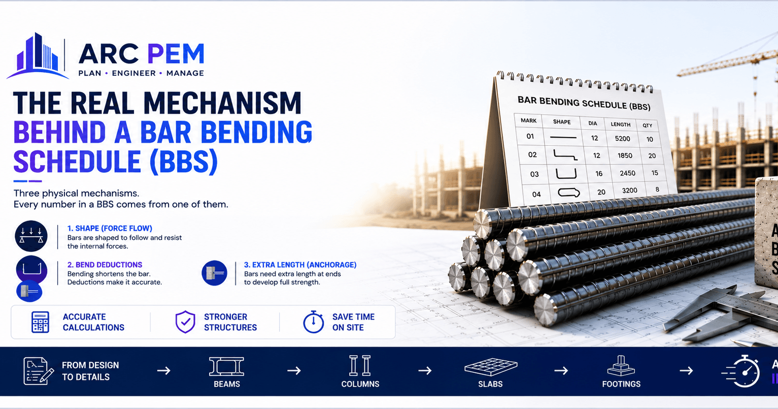
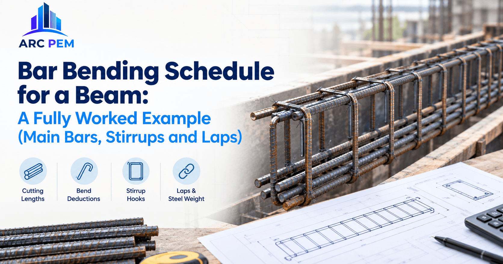
A bar bending schedule (BBS) for a beam lists every bar mark in the beam with its diameter, shape, number, cutting length and weight, so the bar-bender knows exactly what to cut and the store knows exactly what to issue.
In our last post we showed that BBS numbers come from three mechanisms: force diagrams (which set the shape), bend geometry (which sets the deductions) and bond stress (which sets anchorage and laps). This post puts all three to work on one simply supported beam, so you can see exactly where each number in the schedule comes from.
The Beam
| Item | Value |
|---|---|
| Section | 300 × 450 mm |
| Clear span | 4.0 m between two 300 mm wide columns |
| Materials | M25 concrete, Fe500 steel |
| Clear cover | 25 mm |
| Bottom bars | 3 nos. 16φ |
| Top (hanger) bars | 2 nos. 12φ |
| Stirrups | 8φ @ 150 mm c/c, 135° hooks |
Conventions used in this example:
- All dimensions are out-to-out.
- Bend deduction is 2d for each 90° bend.
- Stirrups follow the SP-34 convention our calculator uses: a 9d allowance for each 135° hook, and deductions for the three effective 90° corner bends.
- The end return on main bars is 12d. This is a detailing assumption, so use the value on your own drawing.
- Weight per metre = d² ÷ 162, which gives 1.580 kg/m for 16φ, 0.889 kg/m for 12φ and 0.395 kg/m for 8φ.
Step 1: Bottom Bars (16φ)
Each bar runs the clear span, then continues into each column to within 25 mm of its far face, then turns 90° and returns 12d.
- Straight length = 4000 + 2 × (300 − 25) = 4550 mm
- End returns = 2 × 12d = 2 × 192 = +384 mm
- Bend deduction = 2 bends × 2d = 2 × 32 = −64 mm
- Cutting length = 4550 + 384 − 64 = 4870 mm
- Weight = 3 bars × 4.870 m × 1.580 kg/m = 23.09 kg
This is where the third mechanism, bond stress, shows up. Using the formula from the last post, development length for 16φ in M25 and Fe500 is about 48.6φ, or roughly 777 mm (the working is in Step 4). Only 275 mm of straight bar fits inside a 300 mm column after cover, so the bar cannot be developed as a straight run. The 90° bend and return provide the rest of the anchorage. IS 456 cl. 26.2.2.1 credits a standard bend with an anchorage value of 4φ for each 45° of bend, so a 90° bend is worth 8φ. The anchorage actually required at the support is a detailing decision, so follow your structural drawing.
Step 2: Top Hanger Bars (12φ)
The hanger bars run the same length and are anchored the same way.
- Straight length = 4550 mm
- End returns = 2 × 12d = 2 × 144 = +288 mm
- Bend deduction = 2 × 2d = 2 × 24 = −48 mm
- Cutting length = 4550 + 288 − 48 = 4790 mm
- Weight = 2 bars × 4.790 m × 0.889 kg/m = 8.52 kg
Step 3: Stirrups (8φ)
- Stirrup size a × b = (300 − 2 × 25) × (450 − 2 × 25) = 250 × 400 mm
- Perimeter = 2 × (250 + 400) = 1300 mm
- Hook allowance = 2 × 9d = 2 × 72 = +144 mm
- Corner deduction = 3 effective 90° bends × 2d = 3 × 16 = −48 mm
- Cutting length = 1300 + 144 − 48 = 1396 mm, which is the same as 2(a + b) + 12d
- Number of stirrups = (4000 − 2 × 50) ÷ 150 + 1 = 27 (first stirrup 50 mm from each column face)
- Weight = 27 × 1.396 m × 0.395 kg/m = 14.89 kg
A note on the corners. Our earlier post described a stirrup as having four 90° corners. In a closed link made from a single bar, the corner where the two hooked ends meet is formed by the hooks themselves, so the SP-34 convention counts three effective 90° corner bends plus the two 135° hooks.
Published stirrup formulas also differ by convention. Some use a 10d hook, some count four corners, and some deduct for the 135° bends as well. The difference is a few tens of millimetres per stirrup, but across 27 stirrups per beam and hundreds of beams it adds up. For example, counting four corners and deducting for both hooks would give 1332 mm instead of 1396 mm, a 64 mm gap per stirrup. The important thing is to pick one convention and apply it consistently.
Step 4: Where Laps Come In
This beam is only 4.0 m long, so each bar fits in a standard 12 m length and needs no lap. If it were part of a continuous run over 12 m, you would add a lap at the joint.
For 16φ bars in M25 and Fe500, IS 456 cl. 26.2.1 gives development length as:
Ld = (φ × 0.87 fy) ÷ (4 × τbd)
- For M25 plain bars τbd = 1.4 N/mm², increased by 60% for deformed bars, so τbd = 2.24 N/mm²
- 0.87 × 500 = 435 N/mm²
- Ld = 435 ÷ (4 × 2.24) × φ = 48.6φ, which is about 777 mm for 16φ. Tables round this up to about 49φ.
A lap in flexural tension should be at least the larger of Ld and 30φ (IS 456 cl. 26.2.5.1). Here Ld governs, since 30φ is only 480 mm, so the lap is at least 780 mm. Place it away from the highest-stress zones, which means not at midspan for bottom bars.
Step 5: The Schedule
| Mark | Dia | Shape | No. | Cutting length (mm) | Total length (m) | Weight (kg) |
|---|---|---|---|---|---|---|
| B1 | 16φ | L-bend both ends | 3 | 4870 | 14.61 | 23.09 |
| T1 | 12φ | L-bend both ends | 2 | 4790 | 9.58 | 8.52 |
| S1 | 8φ | Closed stirrup, 135° hooks | 27 | 1396 | 37.69 | 14.89 |
| Total | 61.88 | ≈ 46.5 |
All figures in this example are illustrative. Always confirm bar sizes, anchorage and spacing against your structural drawing before ordering or cutting steel.
Hand-Detailed BBS vs. a Quick Calculator
The table above is a bar-by-bar detail of the kind a bar-bender cuts to. Our free Bar Bending Schedule Calculator answers a slightly different question: how much steel does this member need, quickly.
It uses the same SP-34 stirrup formula as Step 3, so the stirrups match exactly: 1396 mm each, 27 stirrups, 14.89 kg. For main bars it uses a simpler model: clear span plus an anchorage allowance of Ld factor × diameter at each end, with a default factor of 50d and no bend deductions.
For this beam, using the calculator's published formulas, that works out as:
| Mark | Hand-detailed (above) | Quick calculator method |
|---|---|---|
| Bottom bars, 3 × 16φ | 4870 mm each, 23.09 kg | 5600 mm each, about 26.55 kg |
| Top bars, 2 × 12φ | 4790 mm each, 8.52 kg | 5200 mm each, about 9.24 kg |
| Stirrups, 27 × 8φ | 1396 mm each, 14.89 kg | 1396 mm each, 14.89 kg |
| Total | ≈ 46.5 kg | ≈ 50.7 kg |
The quick method comes out about 9% higher, entirely in the main bars. It allows a full 50d at each end, while the hand method uses the actual 300 mm column and a 12d return. Neither is wrong. The quick method is conservative and suits early quantity take-off and ordering, and you can change its Ld factor to the value on your drawing. The hand-detailed schedule is what you cut to once the anchorage is settled. The calculator does not model cranked bars or continuous multi-span beams, which is why this example is a simple single span.
Sanity Checks
- Cutting length versus drawn length. For a bar with only bends, like B1 and T1, the cutting length must be shorter than the sum of its drawn out-to-out segments. For B1 that sum is 4550 + 2 × 192 = 4934 mm, and 4870 is shorter, as it should be. If a cutting length comes out longer, a deduction is missing.
- Steel density. About 46.5 kg over 0.54 m³ of concrete (0.3 × 0.45 × 4.0) is roughly 86 kg/m³. Rules of thumb for beams are often quoted well above that, so this is on the low side. That is plausible for a short, lightly reinforced span, but it is a prompt to double-check the bar sizes if your beam is heavily loaded.
- Stirrup count. It should land on a whole number once the first-stirrup offset is fixed. Here (4000 − 100) ÷ 150 = 26 exactly, giving 27.
- Unit weights. 16φ = 1.580, 12φ = 0.889, 8φ = 0.395 kg/m. If your weights per metre don't match, check the formula d² ÷ 162.
Common Mistakes in a Beam BBS
- Using the clear span as the bar length. Bars run into the supports, so the cutting length is always longer than the clear span.
- Forgetting cover when sizing stirrups. The stirrup is the beam section minus 2 × cover on each side, not the full section.
- Mixing conventions. Hook length and corner counts vary between references. Pick one and use it for every bar mark.
- Ignoring the first-stirrup offset. Counting stirrups as span ÷ spacing without the offset and the extra stirrup gives the wrong number.
- Skipping the check against the drawing. Anchorage, end returns and stirrup zones are on the structural drawing, and they override any default.
Skip the Arithmetic, Not the Understanding
Now that you've seen where every number comes from, you don't need to repeat it for every beam. Try the free Bar Bending Schedule Calculator for beams, columns, slabs and footings, and compare its output with the hand method above.
And once the schedule is done, the real question is whether the site orders and uses exactly that steel. ARC PEM tracks your BOQ, vendor bills and material purchases against your estimate, project by project, so estimated versus actual steel is always one report away. See how to control steel wastage on site, how a project moves from BOQ to final bill, or book a free demo.