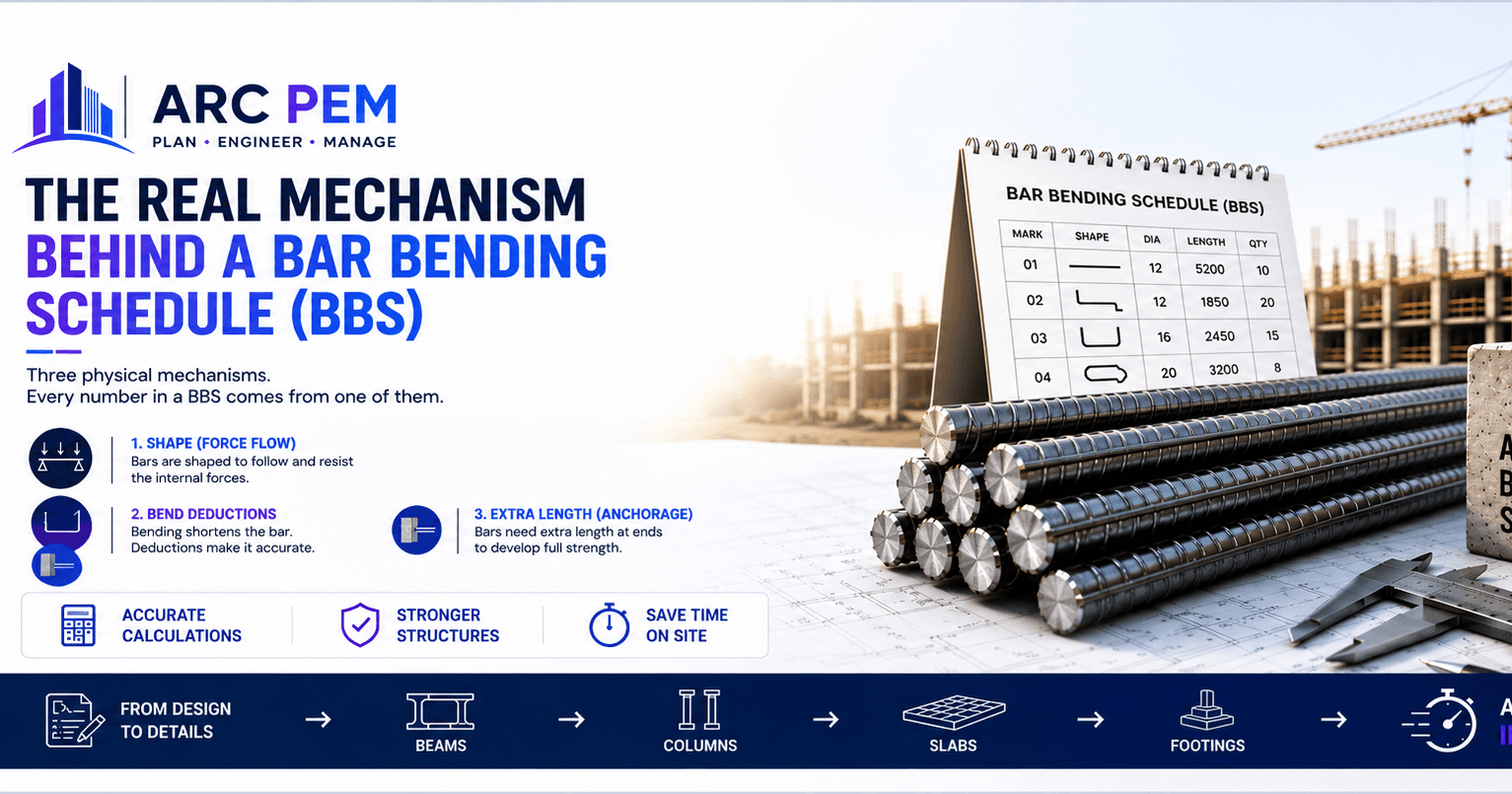
The Real Mechanism Behind a Bar Bending Schedule (BBS)
Most articles explain BBS as a set of formulas to memorize: 2D for a 90° bend, 3D for 135°, D²/162 for weight. But those numbers aren't arbitrary — they're the compressed output of three separate physical processes. Understand those three processes, and the formulas stop being things you memorize and start being things you can derive.
Mechanism 1: Why Bars Have the Shape They Have
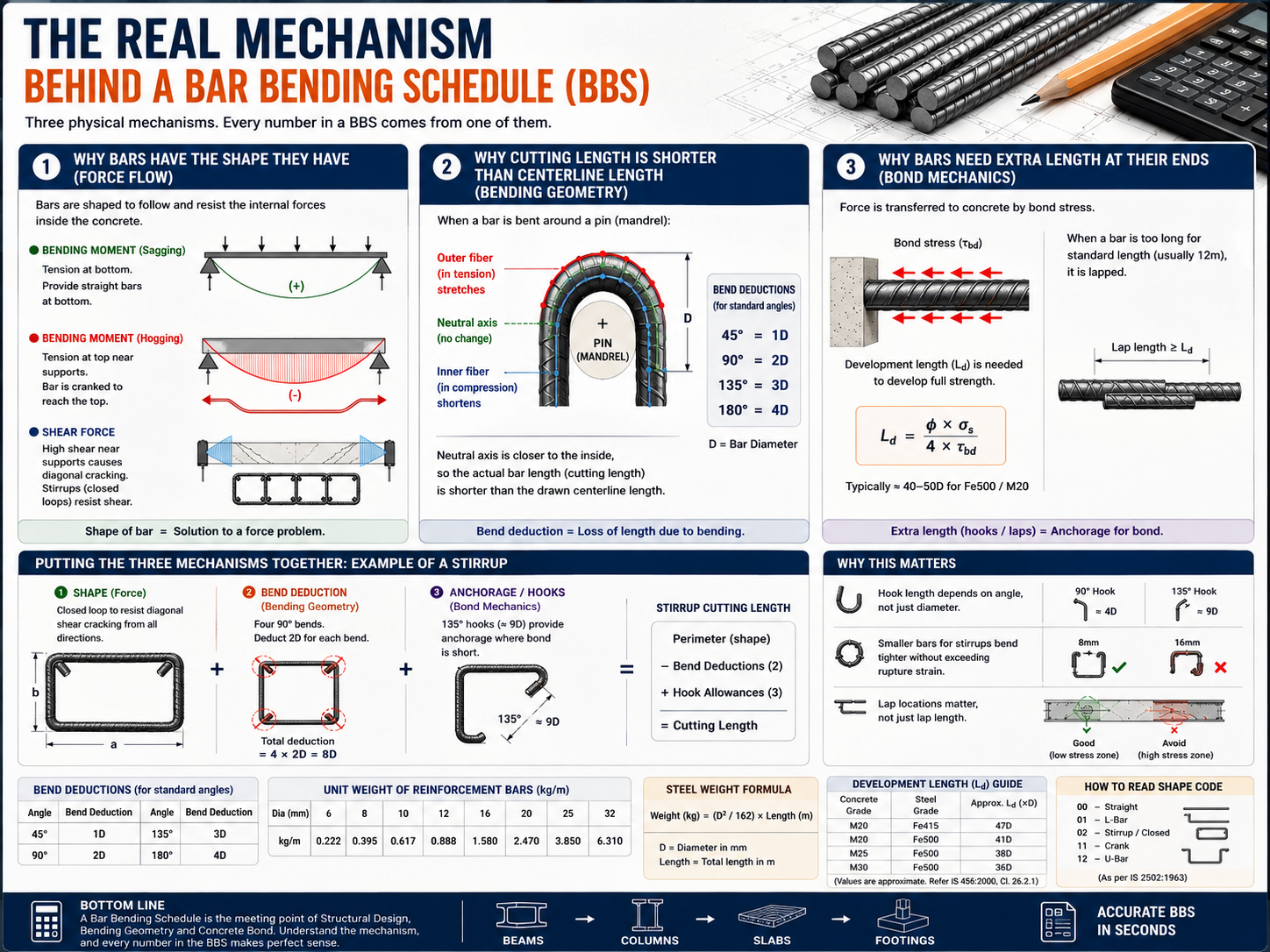
Before any bending calculation happens, a structural engineer has already decided where steel is needed and how much — based on the bending moment and shear force at every point along a beam, column, or slab. At this stage, no shape has been chosen. All that exists is a diagram of internal forces.
The detailer's job is to translate that force diagram into physical steel geometry:
- Where bending moment is positive (sagging), bars run straight along the bottom of a beam or slab, because tension develops on the bottom face.
- Where bending moment becomes negative near a support (hogging), a straight bottom bar is now in the wrong place — so the bar is cranked, bent diagonally upward to cross into the top face exactly where the moment diagram crosses zero. The crank isn't a stylistic choice; it's the bar physically following the sign change of the moment.
- Where shear force is high (near supports, where diagonal cracking initiates), a bar oriented along the span can't resist it — you need a bar oriented to intercept a diagonal crack. That's why stirrups are closed rectangular loops wrapped around the main bars, rather than straight lengths.
In other words, every shape in a BBS — L-bars, U-bars, cranks, stirrups — exists because it is tracing a structural force diagram in physical steel. The shape is not decorative; it's a solution to a specific force problem at that exact location.
Mechanism 2: Why Cutting Length Is Shorter Than Centerline Length
This is the part every BBS table gets right without explaining why: cutting length ≠ the length you'd measure along the bar's centerline on a drawing.
Here's what physically happens when a bar is bent around a pin (mandrel) in a bending machine:
- The outer edge of the bar, away from the pin, is forced into tension — those steel fibers stretch and elongate slightly.
- The inner edge, against the pin, is forced into compression — those fibers shorten slightly.
- Somewhere between the two sits the neutral axis — a layer of steel whose length doesn't change at all during bending.
A drawing measures length along the bar's centerline — the easiest and most obvious reference. But during actual bending, the neutral axis sits closer to the inside of the curve, not at the geometric centerline. That gap between "where the drawing measures from" and "where steel actually behaves as constant length" is the real source of the bend deduction. It isn't a fudge factor — it's compensating for the fact that centerline geometry overstates how much straight bar you need, because part of that length gets absorbed into stretching and compressing during the bend itself.
Where 2D, 3D, 4D actually come from: codes mandate a minimum pin diameter relative to the bar diameter, so the outer fiber doesn't stretch past steel's rupture strain and crack. Given that fixed pin-to-bar ratio, the neutral-axis arc length around a bend can be calculated with basic geometry (arc length = radius × angle in radians) and compared against the straight-line centerline distance a drawing would show. That difference was calculated once, for the standard angles (45°, 90°, 135°, 180°), and published as flat multiples of D so nobody has to redo the trigonometry on site. The formulas are pre-solved geometry, not conventions.
Mechanism 3: Why Bars Need Extra Length at Their Ends
Bend deduction explains what happens at a bend. It says nothing about why bars need extra length at their ends — that's a completely different mechanism: bond stress.
A straight steel bar embedded in concrete doesn't transfer its tension force to the concrete at a single point. It transfers it gradually, along its embedded length, through friction and mechanical interlock between the bar's ribbed surface and the surrounding concrete — this is called bond stress (τbd).
If a bar is cut too short, the concrete can't grip enough of its surface to fully develop the bar's tensile capacity before the bar would simply pull out. The minimum embedded length needed to transfer the full design force is called the development length (Ld):
Ld = (φ × σs) / (4 × τbd)
where φ is the bar diameter, σs is the stress the bar needs to carry, and τbd is the bond strength between that specific grade of steel and concrete. In practice this works out to roughly 40–50 times the bar diameter for common Fe500/M20 combinations — but the exact multiple depends entirely on concrete grade and steel grade, because bond strength is a material property, not a geometric one.
This is also why bars are lapped (overlapped) rather than butted end-to-end when a run exceeds standard market length (usually 12m): a butt joint has zero bond transfer at the joint itself, so the two bars are overlapped for a length at least equal to Ld, letting the concrete's grip carry the force from one bar into the next through the surrounding concrete rather than through direct steel-to-steel contact.
Putting the Three Mechanisms Together: A Stirrup, Traced Through All Three
A rectangular beam stirrup is the clearest example of all three mechanisms acting on one bar.
Mechanism 1 (shape): The stirrup is a closed loop because it needs to intercept diagonal shear cracking from every direction around the main bars — a straight bar physically cannot do this job.
Mechanism 2 (bend deduction): The stirrup has four 90° corner bends. Each one follows the same neutral-axis logic as a single bend — the steel at each corner is being stretched on the outside and compressed on the inside, so the achievable perimeter is shorter than the drawn centerline perimeter by 2D per corner.
Mechanism 3 (anchorage): A stirrup's ends aren't just cut straight — they're bent into 135° hooks (standard hook length ≈ 9D). This exists because a stirrup carries tension right up to its very end, at a point where there's very little concrete around it to grip. A straight cut end would simply straighten out and slip under load. The hook mechanically anchors the end into the concrete core, compensating for the short bond length available at that location.
So a single stirrup's cutting length is the result of all three mechanisms stacked: its rectangular shape (mechanism 1), corrected for how much of its drawn perimeter is "lost" to bending (mechanism 2), plus extra length added because its ends need mechanical anchorage rather than relying on bond alone (mechanism 3).
Stirrup Cutting Length = Perimeter (mechanism 1: shape)
                        − Bend Deductions (mechanism 2: neutral axis)
                        + Hook Allowances (mechanism 3: anchorage)
Every other bar shape in a BBS — L-bars, cranks, straight bars with laps — is some subset of the same three mechanisms. Nothing in a Bar Bending Schedule is arbitrary; every number is downstream of either a force diagram, a bending-geometry constraint, or a bond-stress requirement.
Why This Matters Beyond the Calculation
Once you see BBS this way, a few things that seem like "rules to remember" become obvious instead:
- Why hook length depends on angle, not just diameter — a 135° hook wraps further around the bar than a 90° hook, so it engages more concrete and provides stronger anchorage, which is why codes specify a longer allowance for it.
- Why smaller-diameter bars are used for stirrups even in heavily reinforced beams — thin bars can be bent to a tighter radius without exceeding steel's rupture strain, which matters because stirrups need multiple tight 90° bends in a small space.
- Why lap locations matter, not just lap length — bond stress mechanism only works if the lap sits somewhere the concrete is intact and can actually grip both bars; codes restrict laps from being placed in the highest-stress zones of a member for this reason.
A BBS table looks like arithmetic. What it's actually encoding is force flow, mandrel geometry, and bond mechanics — compressed into a row of numbers so a site engineer doesn't have to re-derive them for every bar.
Once the logic clicks, you don't need to hand-calculate bend deductions and hook allowances for every beam, column, slab, and footing on a project — you just need the right inputs applied consistently. Our Bar Bending Schedule Calculator applies exactly these three mechanisms automatically for beams, columns, slabs, and footings, and generates the cutting length and steel weight in seconds.
Want a follow-up piece walking through how these three mechanisms combine for a full beam — main bars, stirrups, and lap zones — in one worked BBS table?